Heated floors: system solutions for all cases
Batirama.com 05/02/20092
When the supply of energy is ensured, it remains to install the transmitters in the screed, before laying the floor covering. Several solutions are available to you.
Heated floors today are genuine systems offered by manufacturers. These processes therefore include:
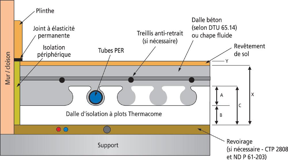
• the plates, which provide insulation while serving as a support for the tubes. They are found with studs forming an embedding groove for the tubes made of synthetic materials, or flat which hold the tubes made of synthetic materials or copper by expansion collars which serve as guides.
• tubes which are mainly in PEX and more rarely in very efficient annealed copper in terms of thermal conductivity, but take longer to implement.
• The coating screed which can be in traditional concrete or in self-leveling concrete for more speed.
• manifolds, which provide regulation, pre-assembled or in kits and offering up to 10 circuits. They can be single or mixed (i.e. allowing the simultaneous supply of the underfloor heating circuit with low water temperature and that of high temperature water radiators). Solutions on the construction site will then be distinguished between wet and dry solutions, with some systems still offering a third way.
Source: batirama.com / Michèle Fourret
The wet solution is a traditional solution so called because water is added to the concrete cover, generally made on site.
1/the wet solution with hydraulic floor
The principle is the circulation of hot water in tubes made of synthetic materials fixed on an insulation slab. The implementation is done under a concrete slab or a fluid screed on which the floor covering will be laid.
2/the wet solution with electric floor for partial heating
The heating is carried out by a constant power cable which is fixed on a plastic frame, the whole placed on a flat insulation slab. Here too, the installation is carried out under a concrete slab or a fluid screed on which the floor covering will be laid.
TO REMEMBER :
Advantage: higher calorific value.

Disadvantages: this solution is reserved for new construction because it is thicker, integrated directly into the frame. The availability of the room in which the PCBT is installed requires at least 7 days of waiting.
Dry solutions are dedicated to renovation. Pipes are laid in (and not on) suitable insulation, which will fit into pre-dug channels. Added to this is a dry screed made up of plaster-based diffusion plates which will replace the concrete cover. These plates are made in the factory and are placed next to each other. They are cut with a circular saw, screwed and glued together.
3/ dry solution with hydraulic floor
In a so-called "dry" solution, without a concrete slab or fluid screed, the floor undergoes a slimming cure since it offers a thickness of around 25 mm (excluding floor covering). The circulation of hot water takes place in tubes made of synthetic material housed in the grooves of an insulation slab, for better distribution and homogenization of the heat.
4/ dry solution on electric floor
This heating system is also very thin (22 mm thick excluding the floor covering) and the heating is carried out by a round self-regulating cable housed in the grooves of an insulation slab.
TO REMEMBER :
Advantages: you have quick access to the room (3 days of waiting is enough)
Disadvantages: the dry solution is reserved for renovation because there are thickness constraints. Heat emission is more delicate with this process and the heat output is approximately 20% lower than the wet solution.
We can speak here of a semi-dry solution, because the pipes are laid on specially designed insulation panels and partially embedded in the slab.
The system is based on the studded panel for screed which is placed directly on the load-bearing support or on thermal and/or sound insulation. The total thickness of the tread is 32 mm. The final coating (ceramic tiles or stone slabs) is laid directly glued on this uncoupling mat, which allows vapor pressure compensation and can be put in place as soon as the screed is accessible to walk. Coating materials resistant to cracking, such as parquet, carpets can also be laid once the imposed residual humidity level has been reached.
Among all the tips, there is one important one that concerns the correct placement of the distribution nurse. If this manifold is placed near the boiler for greater ease, then one finds oneself obliged to lay distribution paths for the tubes, which leads to losing all thermal control of the room crossed before reaching the rooms. which need to be heated. Thus, if the collector is placed in a garage adjoining a kitchen, (very frequent configuration), the tubes pass under the wall separating these two rooms and cover almost the entire surface of the kitchen to then connect to the room to be heated. : the inhabitants will generally complain that they do not have a mastery of the power.
How to avoid the problem?
It is recommended to multiply the collectors instead of installing a single one for large areas (two collectors of 5 circuits each instead of just one of 10 circuits). Even if the initial cost is higher, the comfort that will follow is incomparably better. Another point not to be overlooked is taking into account the coating that will cover the heated floor: the thermal resistance between a PVC floor and a wooden floor is far from being identical and the pitch spacings to be defined are also very different.
*Technical Manager Velta-Eurojauge
♦ GLUED PARQUETS: standard NF P 63-202-1 (Reference DTU 51.2
♦ FLOATING PARQUETS: standard NF P 63-204 (Reference DTU 51.11)
♦ TEXTILE COVERINGS: standard NF P 62-202-1 (Reference DTU 53.1)
♦ PLASTIC COATINGS: standard NF P 62-203-1 (Reference DTU 53.2)
♦ LAMINATED FLOOR COATINGS AND OTHER COATINGS: with their associated uncoupling underlayers, they must have been the subject of a favorable Technical Assessment for use on underfloor heating.
What coating?
When it comes to the coating, it must above all have a thermal resistance of less than 0.15m² K/W, including its possible associated separation layer (under acoustic layer, for example). In general, a PCBT is not recommended with carpet on foam or laminate flooring, as it can peel the carpet and crack the wood of the parquet. If it is an electric radiant floor, given their nature and their thickness, carpets on foam and floating floors are again to be avoided because they limit the diffusion of heat. Moreover, in this respect, the most recommended materials are plastic floor coverings (NF UPEC marked) or even ceramic tiles, natural stones, etc. glued with adhesive mortars. As for the wooden coating, parquet floors in end grain or parquet on joists are not allowed, the air space between the inner face of the slats and the heated floor presenting a much too high thermal resistance. Otherwise, laying a parquet floor on a heated floor is not a problem if certain precautions are taken.
PCBT and parquet |
For the parquet/PCBT couple to work properly, the heating pipes must be covered with a minimum thickness of 30 mm of screed, the latter having no humidity greater than 1.5%. The part must be preheated until reaching the temperature of use (max 26 to 27°), the natural drying of the support having to be supplemented by a setting in temperature of the installation of heating and its maintenance during at least three weeks before the laying of the parquet. Then the heating is interrupted for 48 hours, before a gradual restart at least one week after the laying of the parquet. As for the parquet, its thickness cannot exceed 18 mm so as not to exceed an excessively high thermal resistance threshold. |


